


This technical guide demonstrates how to accurately model the coupling efficiency of an angle-cleaved fiber using OpticStudio. The angled fiber facet and the necessary fiber-mode tilt can be represented through a combination of a Coordinate Break (CB) surface and a Tilted Image surface—one of three proven approaches. Correctly defining these tilt angles is essential to ensure precise and reliable coupling-efficiency results.
We present three effective setup methods, allowing you to select the one that best matches your design requirements and workflow.
- Understanding the geometry of an angle-cleaved fiber
- Creating a baseline system with a normal-cleaved fiber
- Coupling without mode-tilt compensation
- Method 1: CB for mode tilt + Tilted Image for cleave angle
- Method 2: Tilted Image + mode-tilt in Fiber Coupling tool
- Method 3: CB for tilt + negative mode-tilt in Fiber Coupling tool
- Launching from an angle-cleaved fiber
Introduction
In laser and fiber-optic system design, angle-cleaved fibers are often used to minimize back reflections caused by the fiber-air interface. A standard, normal-cleaved fiber typically introduces around 4% Fresnel reflection, corresponding to a 14 dB return loss. By applying an 8° cleave, back reflections can be dramatically reduced—often achieving ~60 dB return loss.
This reduction is critical in high-power laser delivery, where excessive reflections may damage the light source, as well as in sensitive imaging or interferometric systems such as endoscopes and optical coherence tomography.
Understanding the geometry of an angle-cleaved fiber
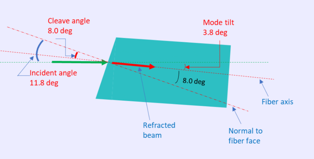
Let’s consider an angle-cleaved fiber with an 8° cleave and refractive index n = 1.47. In the model, assign this refractive index to the Image surface material.
The goal is to tilt the receiving fiber so that its axis aligns perfectly with the refracted beam. This alignment is achieved when the refraction angle (between the refracted beam and facet normal) equals the fiber cleave angle.
Using Snell’s Law:
cppCopyEditsin(angle_in) = n_fiber × sin(angle_refract)
For n_fiber = 1.47 and an 8° cleave, the required incident angle is approximately 11.8°. This ensures the refracted beam travels directly along the fiber axis, maximizing coupling efficiency.
Creating a baseline with a normal-cleaved fiber
We start with a simple single-mode fiber coupling setup: a singlet lens relays light from a source fiber to an identical receiving fiber (NA = 0.1). Using a normal-cleaved receiving fiber:
- Set wavelength to 0.55 µm
- Define aperture: Object Space NA = 0.2
- Apodization factor G = 4.0
Because the system is symmetric, optimal coupling is achieved when object and image spaces are also symmetric. Apply a Pickup solve to mirror the object thickness to Surface 2, then use Quick Adjust to find the smallest spot size at the Image plane.
Fiber coupling analysis (Analyze → Fiber Coupling → Single Mode Coupling) shows ~99.8% coupling. Including Fresnel losses at lens-air surfaces drops this to ~91.5%, and including the fiber-air interface (~4% loss) results in ~88.2%.
Coupling without mode-tilt compensation
Now, introduce an 8° cleave by setting the Image surface type to Tilted (Tangent Y = tan(8°) ≈ 0.140541). Without adjusting the fiber mode, coupling efficiency falls from 88.2% to ~56.4%.
To restore performance, the fiber axis must be aligned with the refracted beam. For our parameters, this requires an 11.8° incident beam angle to produce an 8° refracted beam inside the fiber.
Method 1: CB for mode tilt + Tilted Image for cleave angle
Our recommended approach separates the cleave angle from mode-tilt compensation:
- Insert a CB before the Image surface, Tilt About X = 3.8° to tilt the local Z-axis (and thus the fiber mode).
- Set the Image surface to Tilted, Tangent Y = 0.140541 (8° tilt relative to the tilted local axis).
This arrangement creates an 11.8° incidence angle, restoring coupling to ~88.2%, matching the normal-cleave baseline.
Method 2: Tilted Image + mode-tilt in Fiber Coupling tool
Here, set the Image surface Tilted with Tangent Y = 0.209005 (~11.8°). This achieves the required incidence angle, but leaves the mode misaligned by 3.8°.
In Fiber Coupling analysis, under Settings, apply a 3.8° Tilt About X to align the mode with the refracted beam. Coupling returns to ~88.2%.
Method 3: CB for tilt + negative mode-tilt in Fiber Coupling tool
In this variation:
- Insert a CB with Tilt About X = 11.8° (correct incidence angle, mode tilted with surface normal).
- In Fiber Coupling settings, apply -8° Tilt About X to realign the mode with the refracted beam.
This also recovers coupling efficiency to ~88.2%.
Launching from an angle-cleaved fiber
When launching rather than receiving, the same principles apply—model the angled facet, determine the required incidence from Snell’s Law, and adjust geometry or mode-tilt accordingly.
Conclusion
With proper alignment compensation, an angle-cleaved fiber can achieve coupling efficiencies comparable to a normal-cleaved fiber while delivering greatly reduced back reflections.
The three methods outlined—CB plus Tilted Image, Tilted Image with mode-tilt, and CB with negative mode-tilt—are all straightforward to implement in OpticStudio. The best choice depends on your optimization needs and workflow preference.